| 13N08 TIG Ceramic Welding Nozzle compatible for TIG Welding torch | |||
| Material | ceramic | ||
| Type | |||
| 13N08 | |||
| Size 4 6mm 1/4 inches | |||
| Â | 13N09 | Size 5 8mm 5/16 inches | |
| Â | 13N10 | Size 6 10mm 3/8 inches | |
| Â | 13N11 | Size 7 Â 11mm 7/16 inches | |
| Â | 13N12 | Size 8 Â 13mm 1/2 inches | |
|  | 13N13 | Size 9  16mm  5/8 inches | |
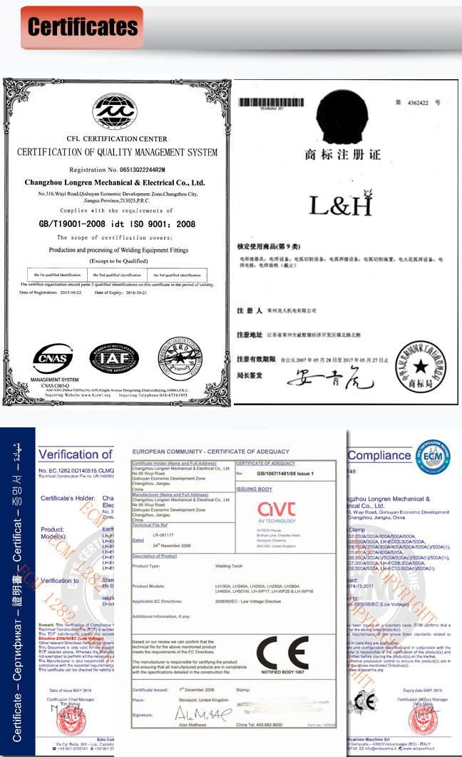
| Certification | ISO9001, CCC, CE, ROHS, TUV | ||


Company introduction:
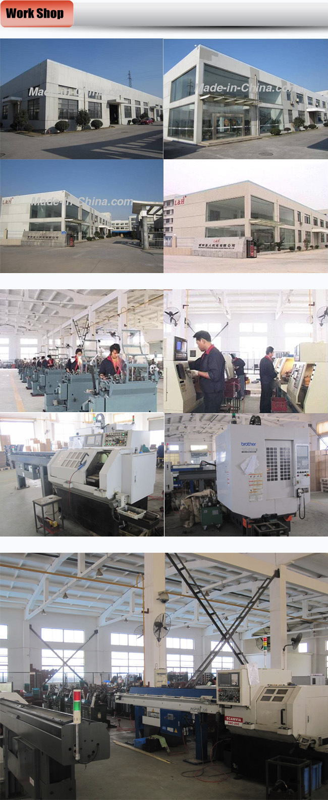
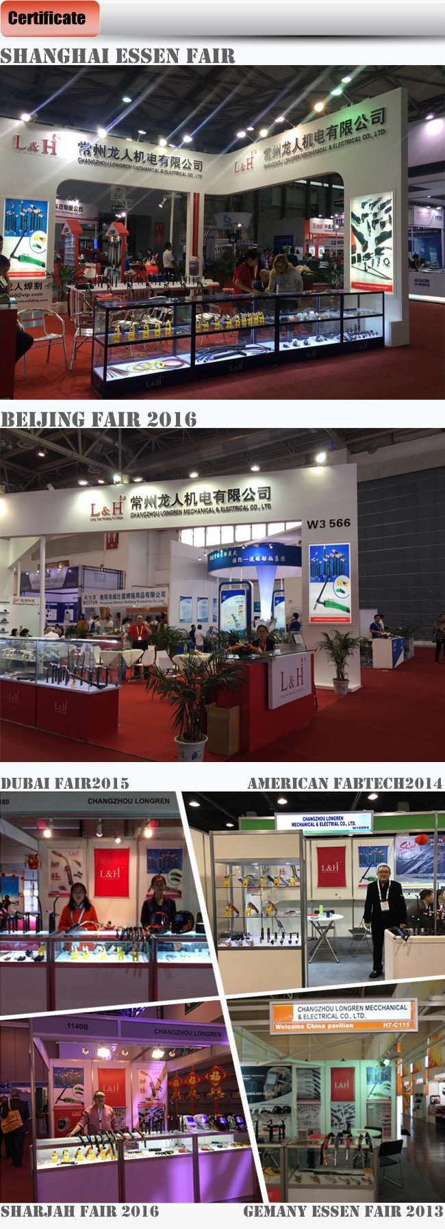
1,ChangZhou LongRen Mechanical & Electrical CO.,LTD is one of leading manufactory of MIG/TIG/Plasma welding torch and parts in China for more than 20 yeas.
2.The company also provides welding accessories, such as electrode holder, earth clamp, welding helmet, cable joint, ceramic backups, electrode rods, welding wire
3.Various products certified by CE and ISO9001:2000 quality management system.
4.99% products are exported to all over the world and gain high reputation from customers on the basis of best quality and Service.
Adjustment of the Main Drive Gap of Wheeled Construction Machinery Drive Axle
1. Check and adjust the bearing clearance of the driving bevel gear. The bearing clearance of the driving bevel gear is generally 0.05-010mm. When the clearance exceeds 0.10mm, it should be adjusted: fix the dial indicator on the axle housing, and the contact of the meter is against the driving gear The outer end of the gear shaft, and then axially pry the upper flange of the gear shaft, the absolute value of the maximum and minimum readings of the dial gauge is the bearing clearance; when adjusting, you can increase or decrease the adjustment gasket between the inner ring of the driving gear bearing and the shaft shoulder. If you add a gasket, the bearing becomes loose, and vice versa.
2. Inspection and adjustment of the bearing clearance of the driven bevel gear. The normal clearance of the left and right bearings of the driven bevel gear is 0.05-0.10mm, which can be adjusted by the adjustment rings on both sides of the differential housing. First, remove the lock plate on the adjustment ring, and then twist the two adjustment rings to adjust (the two adjustment rings must be screwed in or out at the same time to ensure the meshing gap and impression of the gear pair); after adjustment, the driven gear should be It is suitable to rotate flexible and have a little resistance, but there is no loose feeling.
3. The adjustment of the thrust screw of the driven Wheel Loader Bevel Gear. For construction machinery with thrust screws on the back of the driven gear (such as ZL50 loader), the gap between the end of the thrust screw and the back of the driven gear should be 0.20-0.40mm . When adjusting, first loosen the fixing nut, then tighten the screw and back 1/3 turn, and then lock the fixing nut.
4. Inspection and adjustment of the meshing clearance and impression of the driving and driven bevel gears. Inspection methods and standards: When checking the meshing of the driving and driven bevel gears, the tooth surface of the driving bevel gear is usually coated with red lead oil first. In the case of gear meshing, turn the gear with a little resistance, and then check the traces on the Teeth of the driven gear; when meshing correctly, the contact length of the imprint should be about 2/3 of the full tooth length, and the contact traces are 2-4cm from the small end .(Main Drive,Axle Of Sdlg Loader,Pinion Ring Gear,Wheel Loader Bevel Gear)
Main Drive
Main Drive,Axle Of Sdlg Loader,Pinion Ring Gear,Wheel Loader Bevel Gear
Shandong Tianfu International Trade Co.,Ltd. , https://www.tfloaderparts.com