Keywords: PROFIBUS-DP bus; condensate recovery; SI-Pl; When the inverter recovers the condensate, it is necessary to recycle the condensate dispersed in the five tanks (divided water tanks) to the boiler replenishing tank. Since the replenishment flow of the boiler is basically constant, the recovery of the condensate cannot be caused by the overflow of the replenishment tank of the boiler due to the excessive injection flow rate, or the overflow of the distribution tank due to the inability to transport the condensate. Therefore, the constructed condensate recovery control system uses the limit water level of the boiler replenishment tank as the control target. According to the water level of each branch tank, frequency conversion is used to control the speed of the condensate pumps of each sub-tank to control the flow rate of the replenishing tank and achieve condensation. Water is automatically recycled without interruption.
1. System Configuration and Related Settings 1.1 System Configuration The system uses Yaskawa VSG7 frequency converter to connect to the ROFIBUS-DP network with Siemens S7-400 PLC (CPU414-2DP) as the main station. Through PROFIBUS-DP, the main station monitors each frequency conversion. The operating status of the pump, and can remotely set and change its internal parameters.
Yaskawa Inverter can only access Siemens' PROFIBUS-DP network through a special interface card SI-Pl, and it needs corresponding configuration software. The SI-Pl card can be used in Yaskawa's GS, F7, and G7 series. When used in the VSG7 series, it is inserted into the 2CN slot of the inverter and uses the DP bus cable and the bus connector with PROFIBUS-DP. The DP port of the master station (in this case, the CPU 4414-2DP of the S7-400 PLC) is connected.
The topology of the PROFIBUS-DP network system for condensate recovery is shown in Figure 1. Five frequency converters were connected to a dedicated PROFIBUS-DP bus for power supply and the closed-loop control of the condensate pumps of the sub-tank was formed through the monitoring of the water level of each sub-tank. In order to control the number of starters and speed control, the condensate recovery flow is dynamically controlled to ensure that the boiler make-up tank is always maintained at a high water level.

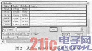
To use the SI-Pl card, configure a universal source data description file GSD (Version 3.1) in the PLC programming software (such as Siemens STEP7). This file can be downloaded from YASGAWA's website under the name YASKOOCA. Gsd). When the configuration file GSD of the SI-Pl card is loaded in the programming software of the PLC, the SI of the Yaskawa inverter can be identified in the system when the ProfibuS-DP network is configured with the hardware configuration function of STEP7 and the relevant hardware is configured. – The configuration icon of the Pl card can be configured as a slave on the network and then the relevant parameters can be set. In this system, the addresses of the slaves of five inverters are 1, 3, 5, 7, and 9, respectively. Slave 1 I/O communication data symbol editing is shown in Figure 2.

1.2 Required settings for using the SI-Pl card To use the SI-Pl card, set the card (ie, slave) address, communication parameters (set uniformly when configuring the master station, that is, the CPU of the PLC), and configure the inverter. Related group parameters, the following are the relevant settings.
1) Set the card (ie slave) address Set the (hardware) address of the drive (as the slave) with 2 (rotary) address switches (one and ten bits for address individually), which should be used with STEP7 The software-configured SI-Pl card of the inverter has the same (software) address on the Profibus-DP network.
2) Setting the communication rate When the communication rate is set on the master station (CPU of the PLC) of the Profibus-DP network, the communication rate of each SI-Pl card on the network is automatically set. The communication rate can be between 9.6kb/s and 12Mb/s, and is usually set at 1.5Mb/s.
3) Inverter related settings Bl-01: The frequency reference input mode is set to 3 (selected communication card).
Bl-02: The operation instruction input mode is set to 3 (selected communication card).
F6-01: When the communication error occurs, the input mode is set to 0 (Continue operation).
F6-02: Set to 1.
F6-03: Set to 3.
Although the main setting adopts the network data communication method, the inverter's "extremely stop" input (S12) is valid in any operation command input mode.
1.3 Data transmission between the master station and the inverter The input and output data of the high-speed I/O data area are each 16B (ie, Byte0 to Byte15, including extended data), where the basic data is each 6B in length.
1) Main data (output data) sent from PDPMaster to VSG7 drive
Byte 0 and Byte 1: Used for operation instruction. When bit0 is "1", it is forward rotation. When bit1 is "1", it is reversed. Bit2 ~ bit7 is equivalent to the setting of H1-01 to H1-06 of the inverter. Functions of control terminals 3 to 8: When bit 8 is "1", it is an external fault. When bit 9 is "1", it is a fault reset. Bit A-bitF bits are unused.
Byte 2 and Byte 3: Used for speed instruction (speed reference setting), transmitted in word units (including low byte and high byte), speed setting resolution is 1/0.01Hz.
Byte 4 and Byte 5: Settings for torque reference/limit.
2) Main data (input data) transmitted from VSG7 inverter to PDPMaster
Byte 0 and Byte 1: Used to monitor the status of the inverter. When bit0 is "1", it is forward running. When bit1 is "1", it is zero speed. When bit2 is "1", it is reverse running. Bit5 is "1" is for reset command reception and so on.
Byte 2 and Byte 3: Used for speed feedback (speed measurement), transmitted in units of words (including low and high bytes), speed measurement resolution 1/0.01 Hz.
1.4 Application If the address of slave No. 1 configured with STEP 7 is 1, the first address of the input byte is IB128, and the first address of the output byte is QB96, then the data transmission between the PDP master station and the inverter is performed. The program is as shown below (including direction commands such as forward, stop, reverse, etc. of the inverter and its drive motor, speed setpoint command, and operation status and speed feedback value monitoring).
AI10.2 reset/stop command signal is "1"
ANI10.0 forward command signal is "0"
The ANI10.1 inversion instruction signal is "0"
LW#16#0000 Load decimal 0 to totalizer 1
TMW100 reset MW100
TMW108 reset MW108
TPQW96 stops with direction word "0"
TPQW98 speed setting value is "0"
AI10.0 forward command signal is "1"
The ANI10.1 inversion instruction signal is "0"
Bit0 of SM100.0MW100 is set to "1"
Bit1 of RM100.1MW100 is set to "0"
The LMW100 is loaded with the direction word TPQW96 forward and the QB96 bit0 is set with "1".
LW#16#1400 Load Decimal 5120 to Accumulator 1
The TPOW98 sends the speed setpoint word AI10.1 reverse command signal to "1"
ANI10.0 forward command signal is "0"
Bit1 of SM100.1MW100 is set to "1"
Bit0 of RM100.0MW100 is set to "0"
LMW100 load direction word TPQW96 reversed, bit 1 of QB96 was "1"
LW#16#1400 Load Decimal 5120 to Accumulator 1
PQW98 sends to speed setpoint LPIW128 Loads the drive status word into the status word intermediate variable AM108.0 of the TMW108 inverter. The forward running signal is “1†= Q10.2 Forward running signal AM108.2 Reverse running The signal is "1" = Q10.2 Reverse run signal AM108.1 Stop signal is "1" = Q10.1 Stop signal light OM108.0 Forward run signal is "1"
OM108.2 or reverse operation signal is "1"
The speed feedback value of LPIW130 loaded into the inverter The intermediate variables of the speed measurement of the TMW110 Inverter The statement table program of STEP7 above can also be expressed in ladder diagram. In addition, another programming method of data communication is to call a function module: the PLC master performs data reading and writing operations to each slave station through system functions SFC14DPRD_DAT and SFC15 (DPWRDAT).
2. Controlling process The objective of the condensate return transformation is to: Condensate water distributed in five places shall be continuously sent back to the replenishment tank in accordance with the need of the replenishment flow of the boiler, as the replenishment of the boiler, and be recycled. Through the recycling of condensate water, the preparation cost of boiler replenishment can be reduced, and coal loss can be reduced.
2.1 Control Process 1) Overall Control Concept In the process of system operation, boiler fill water level (LG) is taken as the main monitoring object, and condensing water tank level (LLn) is used as the feedback signal. When the water level of boiler fill tank is lower than LG, it will The condensate pump that meets or exceeds LLn is turned on and replenish water to the make-up tank. When the water level of the boiler make-up tank is equal to =LG, the water pump with the higher water level in the condensate tank is kept to continue supplying water to ensure that the condensate water tank does not overflow. This part of the condensate water is stored in the capacity of the LG~LGmax(refill tank limit water level) of the make-up water tank. In order to ensure that the amount of water in the make-up water tank meets the boiler water requirements.
2) When the condensing water level reaches the lower limit, the condensate pump stops. The condensing water tank is set to the lowest water level LLmin. When the water level reaches this level, the condensate pump stops.
3) Condensate return process control Real-time monitoring of the water level of each condensate tank, in accordance with the principle of "high open and low close", combined with water level of fill water tank, dynamically control the working status of each condensate pump to control the amount of water supply, so as to ensure that the fill tank is not lacking Water and condensate tanks do not overflow.
2.2 Remote monitoring After using the communication interface card SI-P1 to connect the Yaskawa VSG7 inverter to the open field network PROFIBUS-DP, you can control the running/stopping of the inverter through the PROFIBUS-DP master station, monitor the operating status, change/ Check the parameter settings of the inverter.

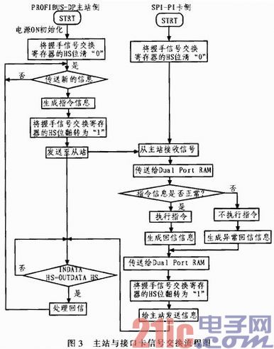
The flow of synchronous control signal exchange between the master station and the slave station is shown in Fig. 3. The system is extensible, providing a platform for remote monitoring and data acquisition of heat exchange station operating parameters. Operating parameters include: power, current, voltage, pressure, temperature, flow, and the operating status of the pump and valve.
3. Conclusion PROFIBUS is an open and independent bus standard that acts as a communication network in machinery manufacturing, industrial process control, and intelligent buildings. Among them, PROFIBUS-DP is mainly used for field-level high-speed data transmission and completes the communication tasks between automatic control systems (such as PLC, PC, etc.) and distributed field devices (I/Os, drivers, valves, etc.) through high-speed serial buses. .
We are experience in the manufacture pressurised columns for the petroleum, LNG, petrochemical,power generation, chemical. Distillation is a separation technique that utilizes differences in boiling points between two or more chemical substances in their liquid phase. For example, methanol and water can be separated using distillation since the boiling point of methanol is around 65 °C and the boiling point of water is 100 °C. Columns are vertical Pressure Vessels with multiple internal trays or packing that separate liquids and vapors to help generate chemical reactions. Our columns can be lined or unlined, and jacketed or not.
Distillation Column,Distillation Tower,Atmospheric Distillation Column,Carbon Steel Distillation Column
Wuxi NanQuan Pressure Vessel CO.,Ltd , https://www.nanquanvessels.com