I. Analysis of power consumption characteristics of industry users
Petrochemical plays an important role in the development of the national economy and is one of China's pillar industries. Petrochemical refers to the processing industry that uses petroleum and natural gas as raw materials to produce petroleum products and petrochemical products. Petroleum products mainly include various fuel oils (gasoline, kerosene, diesel, etc.) and lubricating oils, as well as liquefied petroleum gas, petroleum coke, paraffin, and asphalt. The process of producing these products is often referred to as petroleum refining, or refining for short. Petrochemical products are obtained by further chemical processing of the raw oil provided by the refining process. The first step in the production of petrochemical products is the cracking of feedstock oils and gases (such as propane, gasoline, diesel, etc.) to produce basic chemical raw materials represented by ethylene, propylene, butadiene, benzene, toluene, and xylene. The second step is to produce a variety of organic chemical raw materials (about 200 kinds) and synthetic materials (plastics, synthetic fibers, synthetic rubber) based on basic chemical raw materials. The electricity use characteristics are generally three-shift continuous production.
Petrochemical industry user equipment classification
category
Major equipment
Note
Non-productive load
Office lighting, computer fax printing and other office appliances, split and central air conditioning, cafeteria rice cookers, blowers, plant road lighting
general
Production load
Atmospheric distillation or atmospheric and vacuum distillation apparatus
general
Production load
Catalytic cracking, hydrocracking, delayed coking, catalytic reforming, hydrocarbylation, hydrorefining, cracking processes for the preparation of ethylene, aromatics and other chemical raw materials device.
important
Safeguarding load
Catalytic cracking device
important
II. Analysis of industry users' participation in peak load limitation
Due to industry specificity, in addition to non-productive and non-continuous production atmospheric pressure distillation workshops (economic loss due to atmospheric pressure distillation at normal pressure), other loads must be notified 10 hours in advance before they can safely produce. ACCIDENT.
Third, the industry users involved in the peak load limiting technology program
3.1 Gap Level IV Participation Scheme
Phase-change peak
Decommissioning of non-productive electricity loads such as air conditioning, office, lighting, etc. in logistics and political work departments
2. Emergency peak shift
Decommissioning of non-productive electricity loads such as air conditioning, office and lighting in logistics departments
3.2 gap level III participation program
Phase-shifting
Discontinue production, air conditioning, office, lighting and other non-productive electricity loads
2. Emergency peak shift
Discontinue production, air conditioning, office, lighting and other non-productive electricity loads
3.3 Gap Level II Participation Scheme
1. Staged peak shift:
1) Deactivate non-productive electricity loads such as air-conditioning, office and lighting (except production scheduling systems);
2) 10 hours advance notice to disable the non-continuous production of semi-finished workshops.
2. Emergency peak shift
Deactivate non-productive electricity loads such as air-conditioning, office and lighting (except production scheduling systems)
3.4 Gap Level I Participation Scheme
Phase-shifting
Arrange the company for maintenance.
2. Emergency peak shift
Discontinued production of atmospheric distillation production workshop
Fourth, the industry users involved in the peak load shifting risk and precautions
1. Abrupt power loss in petrochemical production process, except non-productive load and non-continuous production atmospheric distillation production workshop (emergency pressure limiting atmospheric distillation also has economic loss) Other workshop production systems will emit toxic and harmful substances , causing a great deal of pollution to the environment and causing harm or fatality to people in a wide range; causing explosions with serious consequences.
2. Fire-fighting pumps are security facilities that flammable and explosive chemical companies maintain their pressures and operate normally in the production process. If they are out of power and stop to face fire accidents, they will not be able to rescue them in time. This will result in the expansion of accidents and the property of personnel. More loss.
Therefore, users of the industry should formulate effective emergency plans as early as possible. When participating in the peak shift, they should actively cooperate with the peak implementation, communicate with the power supply companies in a timely manner, and take measures such as maintenance or rotation to avoid the use of compulsory pull-in or remote control equipment to control power cuts and prevent viciousness. When accidents occur, they take the initiative to shoulder social responsibilities while minimizing losses.
V. Functions and Applications of Intelligent Power Monitoring
5.1 System Overview
Shanghai Ankerui Electric Co., Ltd. undertakes the design and implementation of a remote automatic meter reading system project of China Petroleum Building. Using ACREL-2000 type power monitoring system, the monitoring range of the monitoring system is: high-voltage power distribution room, low-voltage power distribution room 1#, and low-voltage power distribution room 2# power meters. One low-voltage power distribution room 1#, 2# has a total of 146 PZ80-E4 instruments from Shanghai Ankerui Electric Co., Ltd.
5.2 User Requirements
The functions to be implemented by the petrochemical enterprise power monitoring system are: remote monitoring of all electrical parameters of the building's high and low voltage distribution systems; real-time interface displays the important electrical parameters of the high and low voltage loops, and high-sensitivity and reliability real-time data refresh rates; See the real-time data and query the current curve diagram (or load curve diagram) of each high-pressure loop and low-voltage inlet and low-voltage important outlet loops; all loops have an electric parameter query report, and can query the second-order history of electric parameters; Reports, according to the needs of management can be appropriately modified report format, can query the energy value at any time.
5.3 Design Ideas
In accordance with the actual needs of the petrochemical companies and the functions of intelligent components, the design of the system is completed. The main functions are: display of a main wiring diagram interface; remote sensing of electrical parameters and over-limit alarm of electrical parameters; event recording, abnormal monitoring of system operation; failure Alarm and operation records; energy report query and printing; history curve, user rights management, high voltage remote control, low voltage main line remote control and other main functions.
The entire system adopts a network distributed structure. The monitoring host is located in the monitoring room. The system adopts an open communication protocol and connects to the communication server through the field bus.
5.4 System Structure
The system adopts a layered distributed computer network structure, namely, a bay layer, a communication layer and a station control layer as shown in the following figure:

The main equipment in the bay is: power meter, switch module and intelligent circuit breaker. These devices are corresponding to the corresponding primary equipment installed in the electrical cabinet, these devices are used RS485 communication interface, through the scene MODBUS bus networking communications, data acquisition on the spot.
The middle tier is mainly a communication server. Its main function is to collect the scattered data at the site collection device and transmit it to the station control layer at the same time. The data exchange between the field layer and the station control layer is completed.
Station control layer: equipped with high-performance industrial computers, monitors, UPS power supplies, printers and other equipment. The monitoring system is installed on the computer to collect and display the operating status of the field equipment and display it to the user in the form of human-computer interaction.
The above network instruments all adopt RS485 interface and MODBUS-RTU communication protocol, and RS485 adopts shielded wire transmission.
5.5 The main functions of the system
First, data acquisition and processing
Data acquisition is the basis of power distribution monitoring. Data collection is mainly completed by the underlying multi-function network instrument to achieve local real-time display of remote data. The signals that need to be collected include: three-phase voltage U, three-phase current I, frequency Hz, power P, power factor COSφ, power Ep, and remote device operating status.
Data processing is mainly to display the electrical parameters collected according to requirements in real time and accurately to the user, so as to meet the requirements of automation and intelligence of the power distribution monitoring. At the same time, the collected data is stored in the database for user query.
Second, human-computer interaction
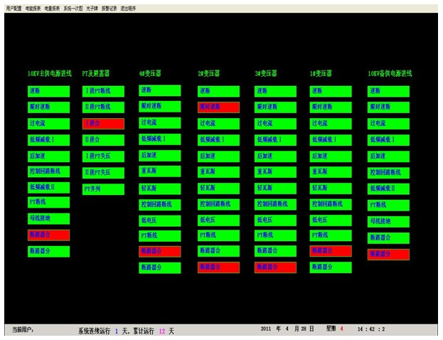
The system provides simple, easy to use, and good user interface. All Chinese interface, electrical main electrical wiring diagram of the distribution system, display equipment status and real-time operating parameters; dynamic refresh of the screen in real time; analog display; switch display; alarm record display.
1, high pressure map:

The high-voltage primary map is the main monitoring screen of the system, which mainly monitors the operating status of the high-pressure loop in real time, and important electrical parameters. Each circuit on the interface shows a red switch on the diagram and green on the switch.
2, a low pressure map:

Real-time display of low-voltage incoming circuit, capacitance compensation, opening and closing loops, real-time refresh load, current, voltage, power and other real-time values.
3, real-time, historical graph:


The function buttons in the interface include time interval selection, refresh curve, mouse zoom, mouse translation, search curve, curve left and right movement in the display surface, and current curve position adjustment. The adjustment of the position of the current in the trend chart is divided into 5 steps, and the user can select an appropriate range according to the size of the query current.
4, electricity, power report

This energy report supports the manual input of time to query the power consumption of any period and any loop. The outlet loops under the same transformer are arranged in the same power report, which facilitates statistical management of management personnel. Department reports can be designed into user-friendly power report formats to extend the work style of the staff.
5, high pressure photonic card:

Display microcomputer protection device power-on, device power-off, device reset, signal return, remote control operation, local operation, modify the protection settings, device self-test error, device over temperature and other signals, the signal jumps with sound and light alarm.
Third, fault alarm and accident recall
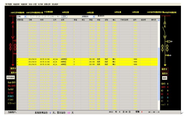
When an operational fault occurs in the power distribution system, an alarm will be sounded in a timely manner to prompt the user to respond to the fault circuit in a timely manner. At the same time, the time and place of the event are automatically recorded to be queried by the user and the cause of the fault is recalled.

Fourth, database establishment and inquiry
It mainly completes remote measurement and remote signal acquisition, and establishes a database to generate reports regularly for users to query and print.
Fifth, user rights management
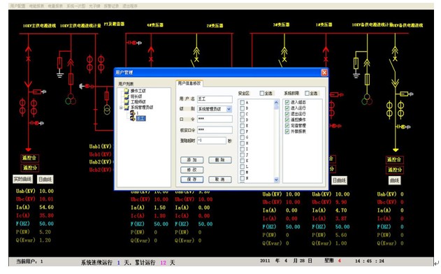
The number of users who can add and remove software according to the buyer's requirements and set the user's rights. For different levels of users, different permission groups are set to prevent the losses caused by human misoperation to production and life, and to realize the safe and reliable operation of the distribution system.

Sixth, the main monitoring products
(1) ACR330ELH meter for high voltage circuit or low voltage circuit
The meter is a power quality analyzer. The main functions are: LCD display, all-electric parameter measurement (U, I, P, Q, PF, F, S); four-quadrant energy metering, multi-rate energy statistics; THDu, THDi, 2-31 times each harmonic wave component; Voltage crest factor, telephone waveform factor, current K factor, voltage and current unbalance degree calculation; Grid voltage and current positive, negative, zero sequence component (including negative sequence current) measurement; 4DI+ 3DO (DO3 overvoltage, undervoltage, overcurrent, unbalance alarm); RS485 communication interface, Modbus protocol or DL/T645 protocol. Dimensions: 120 × 120mm, opening size: 108 × 108mm. Suitable for high pressure important circuit or low voltage inlet cabinet.
(2) ACR220EL power meter with low voltage contact or outlet loop
The main functions of the table are: LCD display, all-electric parameter measurement (U, I, P, Q, PF, F); four-quadrant energy metering, multi-rate energy statistics, maximum demand statistics; 4DI+2DO; RS485 communication interface , Modbus protocol. Dimensions: 96 x 96mm, opening size: 88 x 88mm. Suitable for low-voltage connection cabinets and outlet cabinets.
(3) Low voltage outlet cabinet selection ARD series
The meter measures protection functions such as three-phase current, fixed value query, fixed value setting, overload, phase failure (unbalance), locked rotor, underload, external fault, blocking, undervoltage, 8DI+4DO, power management, and leakage protection , SOE records, a variety of start mode, RS485 communication interface, MODbus protocol / Profibus-DP protocol optional.
(4) Optional APF active filter device for energy-saving products
ANAPF series active power filter devices are connected to the power grid in parallel and detect harmonics and reactive components of the load in real time. PWM inverter technology is used to generate one current harmonic component and reactive component from the converter. The inversion component is injected into the power system in real time, so that harmonic control and reactive power compensation are realized.
Seven, equipment list
No.
name
Model, specification
unit
Quantity
Note
1
Power Meter
Three-phase multi-function power meter
PZ80-E4
only
146
Ankerui
Network multifunctional meter
ACR220EL
only
50
Harmonic table
ACR330ELH
only
678
Open type current transformer
AKH-0.66/K
only
438
Ankerui
2
Monitoring Center duty room
Console
YT-341
set
1
Xianghe
Workstation host
IPC-610L/769VG/E5300/2G/500G/DVD/88 Mini Key+Mouse (Original Machine Standard) 2 Serial Ports
station
1
Advantech
monitor
L197WA
station
1
Lenovo
UPS power supply
C1K/1KVA
station
1
SANTAK
printer
HP 1108 A4 format
station
1
HP A
system software
Genuine Microsoft WINDOWS XP/SP3
set
1
Microsoft A
Industrial network switch
D-LINK 16 ports
station
1
D-LINK
Industrial Serial Server
NPORT5232I RS485 interface × 2 with light isolation
station
4
MOXA
Industrial switching power supply
KDYA-DG30-24K
only
4
Huali
Power Management Software
System Configuration Software Acrel-3000V6
set
1
Ankerui
Power Management Software
Data Storage Software Acrel-dbSQL
set
1
Ankerui
Power Management Software
Energy Management Software Acrel-EnerSys
set
1
Ankerui
Power Management Software
Device Driver Software Acrel-Driver
set
1
Ankerui
Photoelectric converter
Single mode photoelectric conversion HTB-1100S(25km)
only
8
3
Engineering Materials
Communication cable
Single-mode 4-core fiber
km
2
Communication cable
Shielded twisted pair RVVSP 2*0.75
km
0.2
Sail
Communication cable
BVR 1.5mm
km
4
Engineering materials
Towboards, conversion lines, lines, signs, etc.
set
1
Measuring box
A total of 4 units are required to be installed in each substation.
only
4
Fiber Optic Accessories
Includes welding, pigtails, flanges, jumpers, etc.
set
4
4
Construction and commissioning
Communication cable laying
Meter
2200
Comprehensive debugging
People/day
25
Equipment transportation costs
item
1
training fees
item
1
Construction renovation costs
item
1
Eighth, concluding remarks
The system implementation of the petrochemical complex project is to centrally monitor the software of the microcomputer, read the information volume of each meter in the power distribution room, and realize the centralized monitoring of the power meter of the power distribution room by the monitoring machine. Can understand the entire building's power system status, which is also useful for scheduling commands under power system accident conditions. Through the monitoring system software to achieve control of field instruments; to achieve the distribution room data acquisition, monitoring and management; at the same time with alarm processing and other functions. Friendly interface operating system and easy operation make the system more user-friendly. Moreover, the system assembles the hardware equipment into a general-purpose switch cabinet designed by itself to realize centralized management, and also facilitates the maintenance and replacement of the system, and improves the modularity, standardization, and hiberarchy of the product, facilitating the expansion of the system. The use of configuration software reduces the dependence of power equipment status monitoring on manpower, reduces manpower costs, and improves economic efficiency. Provides a scientific and accurate basis for the production operation and management of the power system.
references
[1] Ren Chengcheng and Zhou Zhong eds. Principle and Application Guide for Power Electronic Measurement Digital Instrument China Electric Power Press, 2004.4
[2] Zhouzhong Ankerui power monitoring configuration software in the distribution system.
[3] Petrochemical industry peak power limiter technical guidance.
Flux Cored Welding Wire Production Line
flux-cored wire Production line main processing
(1) steel strip rewinding: pay off strip →constant tensile rack→ spool take up
(2) forming and rough drawing machine: pay off → constant tensile rack→ forming into U shape-→servo powder adding system →forming and reduce diameter→ LZ6/500 drawing machine → spool take up
(3) pay off → LZ10/400 reduced diameter →polishing machine →spool take up
(4) the layer winding: about 15-25KG each packing
Flux Cored Welding Wire Production Line,Flux Cored Wire Drawing Machine,Seamless Flux Cored Wire Production Line,Seamless Flux Cored Wire Product Line
Jiangyin Wanyi Machinery CO.,Ltd , https://www.wydrawmachine.com