(1) The sensor measuring circuit is simple, there is no flow blocker and the location of the easily stagnant medium;
(2) The materials that come into contact with the medium can meet the frictional forces of the solid particles in the cement slurry at high flow rates and the slump function of the chemical slurry;
(3) No shortage of fast response performance and high measurement accuracy;
(4) It can comply with the harsh environment of high temperature, humidity and high dust in the site. In the viscous liquid flow instrument product, the electromagnetic EMF is free from the effects of fluid temperature, pressure, density, and viscosity. The internal flow of the electromagnetic flowmeter is straight and smooth, and the electric measurement is performed directly. The response speed is fast and the detection unit has no game parts. It will produce dripping body surface, high measurement accuracy, lining can adopt PTFE plastics and alumina ceramics, strong and excellent slump resistance, etc. [3]3. In recent years, it has become the preferred instrument for grouting project flow measurement.
1 Working principle The principle of the electromagnetic flowmeter (see Figure 1) is based on Faraday's law of electromagnetic induction. The medium to be measured flows in a direction perpendicular to the lines of magnetic force, so that an induced electromotive force E is generated due to the biased flow perpendicular to the medium flow and magnetic lines of force.
Where: E is the electromotive force, V; ugly is the magnetic induction, T; D is the inner diameter of the measuring tube, m; the average flow velocity is measured as the measured medium, m/s. The volume flow rate of the measured medium is Q.


It can be seen that the induced electromotive force E is proportional to the flow rate Q of the measured medium. It is related to the induction strength and the measurement of the inner diameter D, but it has nothing to do with the change of other physical parameters. The transmitter output E of the measurement and preparation is a weak alternating signal, which contains various disturbance components, and the internal resistance of the signal changes up to tens of thousands of Q. Therefore, the request changer is a high input impedance and can suppress all kinds of disturbances. Components of the exchange mV changer. Change the induced emf to the 4-20mA merge signal. The changer is composed of a high input impedance differential amplifier, a main amplifier, an orthogonal disturbance suppressor, a phase sensitive detector, a DC amplifier, a Hall multiplier, etc., and the output signal current is
Where: Io is the output signal current; K is the instrument constant. 2 Exercising of EMF in Grouting Engineering Figure 2 shows the main process flow of the grouting process. In order to carry out appropriate control during the completion, the water and cement slurry in the course of completion must be measured and controlled.

Drilling and washing holes: It is important to drill holes in the rock formation from top to bottom in the completion of the grouting, until the single hole final hole, with a lot of water to wash the hole, to clear the backwater, no flow measurement point, so do not relax discussion . The water pressure test of the knots: Wash hole closes, the lower orifice tube, and the sealing orifice, and send water to the orifice with the pressure required by the design, determine the corresponding flow value, and calculate the permeability of the rock mass. The planning results are linked to the evaluation of the infiltration characteristics of the rock mass and the improvement of the grouting material. This measurement point is very important and sensitive. Accurateness is an important indicator. Water has the necessary conductivity and meets the measurement requirements of EMF. It is necessary to focus on the caliber of EMF because the water pressure experiment and grout use the same EMIr. Grouting: After the water pressure test, the grout pump hydraulically feeds cement slurry of required water-cement ratio (eg 3:l, 2:1, 1:1, O.8:l, O.5:1) to the hole. A part of the slurry arrives at the crevice and opens, and the rest of the slurry goes back out of the hole through the slurry pipe and flows back to the slurry mixer. Under the pressure of the end, when the injection rate is not more than 0.4L/nfin, 30nfin is continuously poured; or Not more than 1L/n"fin, continuous filling 60rffm, grouting can end. Each drilling equipment requires two EMF divorce records recorded in, return flow, grouting amount is equal to the amount of pulp minus the return of slurry, on-site pipeline and The EMF installation schedule is shown in Figure 3.

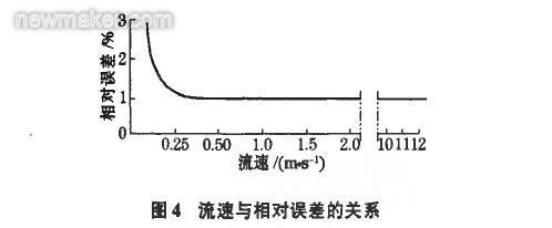
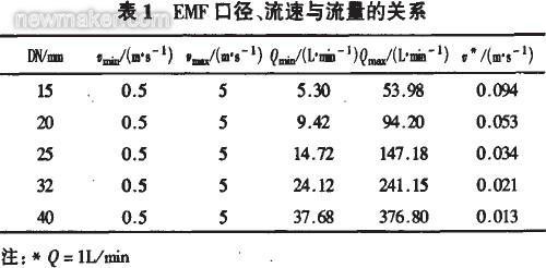
Since the pump of the field grouting pump is mostly 6/h (100L/n[1mm]), the EMF range is selected as 100L/nfm. It can be known from the measurement principle of EMF that the lower limit of the flow rate is the same as the noise or offset signal noise. The resolution is determined by S/N (signal and noise), and the upper limit is determined by the wear of the inner lining of the measuring tube and the economic speed of the piping. As the cement slurry contains solid particles of cement, the abrasion of the EMF lining and the electrode is inferred, and the flow rate is selected to be ≤ 5m/s. On the other hand, the cement slurry has the characteristics of easy adhesion, precipitation, and scaling, so the inside of the EMF measuring tube The flow rate should not be lower than O.5m/s to function as a self-cleaning function for the electrode and the inner liner. When the actual flow rate in the measuring tube is less than 0.1m/s, the induced electromotive force has become very weak (a few tenths of a few turns). At this time, the influence of noise gradually becomes dominant, and even the electromotive force is swallowed by the flow rate and the relative stain. The connection diagram (Figure 4) shows that in order to ensure the accuracy of the instrument detection, the flow rate should be greater than O.5m/s. Therefore, the recommended flow rate range is O.5. 5m/s.

When the grouting is completed, the amount of absorbed liquid is flat at 0.100 L/min, and the corresponding flow field of the EMF on the incoming and returning slurry is 30-100 L/min. From the contact tables of the flow rate, flow velocity, and caliber (Table 1), it can be seen that the EMF caliber is selected. DN25 matches. The measurement area of ​​DN25 is 14.72-147.18L/min. At the same time, the diameter of DN25 and the site of grouting pipeline are the same. When it is installed, there is no need to change the diameter. At the same time, the EMF's time constant should also be set smaller, flat in l-3s, to increase the speed of measurement.

Sealing: After the grouting is completed, the squeezing and sealing are performed in accordance with the completion skill and there is no flow measurement point, so the discussion is not relaxed.
3 Application-oriented matters 3.1 Impact and disposal of finished process In accordance with the principle of cyclic grouting, the return slurry shall flow back to the mixing tank, and the flow of the slurry in the divorce metering and return pipe shall be adopted for the two legs (as shown in Figure 3). However, some users remove the EMF on the return pipe. The return pipe is willing to promise that a three-way pipe is directly connected to the EMF low energy feed pipe. The return slurry will not return to the mixing tank and adopt an EMF measurement grouting amount [5]. In the small amount of rock slurry absorption and the end stage of grouting, the flow rate of the slurry and liquid through the EMF is very small, far below the lower limit of the flow rate of the ETa, the S/N ratio is very small, and the measurement stain is as high as 50%. .
3.2 Influence of measuring the amount of slurry attached to the pipeline and disposal Once the grouting has been completed, the residual slurry in the EMF measuring tube must be removed on time. Otherwise, the cement slurry can easily generate discordant levels of cementation in the measuring tube, even the closed coffee measuring tube and adhering. Grout piping. The adhesion layer in the F2vIF measuring tube will cause an additional relative stain, Δε, which is confirmed by the fact that the stain caused by it is very large. Assuming that the thickness is the same, Δε is given by (5).

In the formula: %, diagnosis is the attachment and the conductivity of the measurement solution; t is the thickness of the attachment; d is the diameter. The percentage of cement particles is very different from that of the cement slurry because the electrical conductivity of the cement layer is extremely low. When the thickness of the attached material is required, the △ε will be large.
CCMC has redesigned the pressure screens used for the liquid-solid separation of fibrous non-abrasive materials with efficiency and simplicity in mind. The following is a list of unique standard features.
Features
Easy access through large front and back doors
Easy, Quick-change, vapor proof EPDM rubber door seals
Quick screen change-out
Simple rugged one handle door latch
316 stainless steel screen with UHMW side supports
UHMW feed nozzle, replaceable from outside
Built-in efficiency and simplicity
The liquid-solid separation and dewatering gravity screens that CCMC builds have been designed for efficiency of operation and simplicity of maintenance. The following is a list of unique features.
Standard Features
Built-in tapered headbox
304L stainless steel construction
Flow distribution baffle
Mounting stanchions
Rugged replaceable screen panel with seals
No motors or rotating parts
Screen Box,Corn Milling Gravity Screen,Polished Finish Gravity Screen,Fiber Fractionation Pressure Screen
Changchun Meichen Machinery Co., Ltd. , https://www.ccscreenbox.com