1 Overview A single flange level transmitter is a field transmitter that is mounted directly on a pipe or container. The single-flange level transmitter can accurately measure the level and density of various containers and is divided into flat flanges and plug-in flanges because the isolation diaphragm is in direct contact with the liquid medium. It is not necessary to draw the positive pressure side with a pressure guiding tube, so it is suitable for the measurement of high temperature, high viscosity, easy crystallization, easy precipitation and strong corrosion and other media.
At present, there are many methods for measuring the liquid level in a closed container. Common measuring instruments include a magnetic flap level gauge, a double flange differential pressure transmitter, a single flange differential pressure transmitter, a differential pressure transmitter, and a radar liquid. Position meter and so on.
The magnetic flip level gauge loses its magnetism in some environments and causes the level gauge to malfunction. The radar level gauge has high accuracy, but the investment is large. At the same time, due to the large number of signal interference sources in the initial stage of operation, it has a great influence on the measurement. Requires frequent removal of false signals; differential pressure transmitters have lower costs, high measurement accuracy, and less interference sources, so the use of differential pressure principle to measure the liquid level in closed containers is more commonly used.
2 Single Flange Level Transmitter Single Flange Transmitter is divided into two kinds: plug-in type and flat type. The measurement principle and installation method of the two types of transmitters are basically the same, but the measurement data of the transmitter is measured under different process conditions. The impact is very large. Taking the salt condensate flash bucket as an example (see Figure 1), A is the steam condensate inlet, B is the flash steam outlet, and C is the single flange transmitter installation location. D is the steam condensate drain pipe, and point E is the negative pressure side pressure point of the single flange transmitter.
In the process of instrument selection. We often ignore the effect of water flow on the pressure. If point A is perpendicular to the tangent line of the bucket, the water in the bucket will not form a vortex, but the water column falling from point A will affect the measurement of pressure at point C, resulting in a single flange transmission. The positive pressure side measurement data is not stable; if point A is not perpendicular to the bucket tangent line, the water in the bucket will form a vortex, regardless of the position of the C point, it will cause the single-flange transmitter's positive pressure side measurement data to be distorted. Taking into account the flash condensation efficiency of steam condensate, the inlets parallel to the tangential direction of the A point and the barrel are generally used. This will inevitably create whirlpools in the barrel. The issue of transmitter selection is crucial. 
3 Plug-in Single Flange Transmitter and Flat Flange Transmitter Our company chose the plug-in single-flange transmitter to be used after it was put into use. Frequently low, due to inaccurate level gauges, automatic adjustment of the liquid level control valve can not be normally used, only rely on the operator to observe the glass level gauge on the spot to adjust the barrel level, increase the amount of T does not say, Liquid level control is also not good, flashing efficiency is low, and it has a great impact on production.
Began to suspect a single-flange transmitter problem, the test found that the transmitter in the laboratory everything is normal. After careful observation of the site process piping. It was found that the measured value of the transmitter was suddenly large and small, and it was considered that the water flow caused the transmitter's positive pressure measurement data to be distorted. 
As shown in Figure 2, point A is the condensate inlet pipe and point B is the plug-in single flange transmitter installation position. The inlet pipe is in the direction of the tangent of the barrel, and the vortex is formed in the barrel. The positive pressure diaphragm of the insert type single flange transmitter is in the vortex flow. The impact of the water flow causes the pressure of the transmitter's positive pressure measurement point to be unstable and the measurement data to be distorted. Since the steam condensate bucket is a pressure vessel and cannot be reformed at will, the only way to solve the problem is to replace the transmitter.
As shown in Fig. 3, points A and B are the same as in Fig. 2. C is a static water zone between the tank wall and the pressure-receiving point. The presence of this static water area isolates the turbulence in the tank and the level of the flat flange. The transmitter positive pressure diaphragm, so that the transmitter pressure measured at point B is not affected by the whirlpool water pressure inside the barrel. After confirming the good plan, our company contacted the manufacturer and converted the plug-in single-flange liquid level transmitter to the flat flange liquid level transmitter. After modification, the level data of the condensate balance tank was completely eliminated. In the distorted case, the instrument is running smoothly. 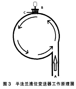
Whether it is to insert a single flange liquid level transmitter or flat flange liquid level transmitter in the final analysis belong to the differential pressure transmitter, the principle of which is to measure the liquid level is calculated by the formula P = pgh medium full of liquid The pressure at the time, then the transmitter's range after the negative migration through the differential pressure to calculate the height of the liquid level in the container. Therefore, only if the pressure measurement is accurate, the liquid level may be correct. The advantage of inserting a single-flange liquid level transmitter is that it is less likely to occur in high-viscosity, large-particle-medium media, but it appears to be weak in response to severe fluid shocks. To sum up, in the process of instrument selection, we not only consider the price, brand, material and other issues of the instrument. It is also crucial to consider whether the working conditions in the instrument's area can make it stable and reliable.
Silicone Coated Fiberglass Braid Sleeve for Cable Insulation

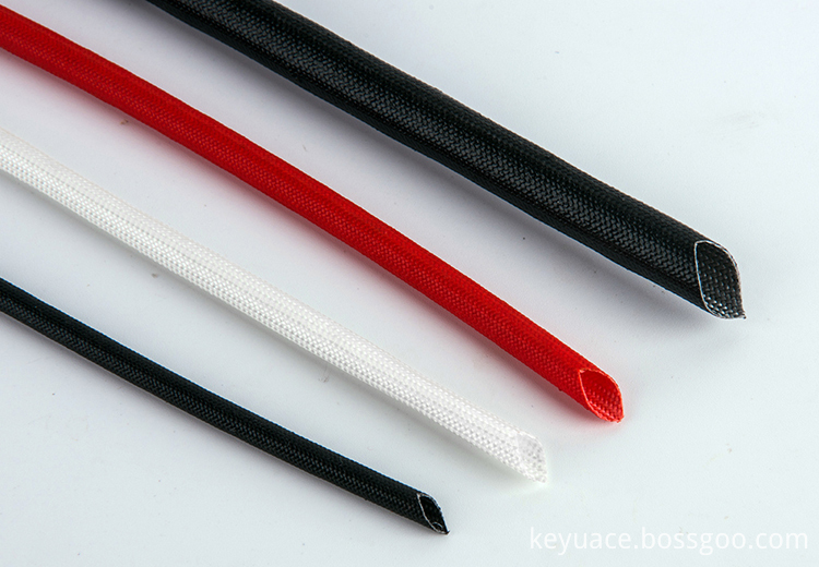
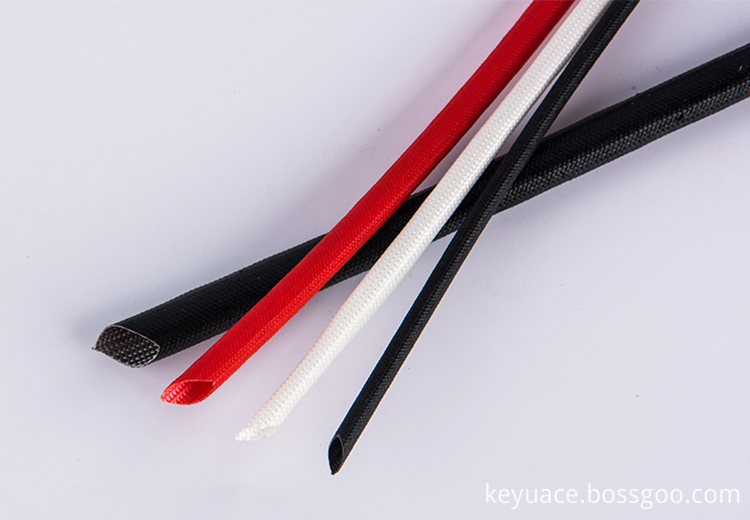
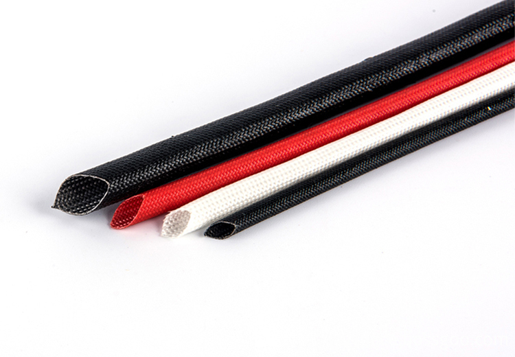
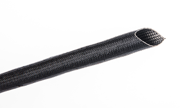
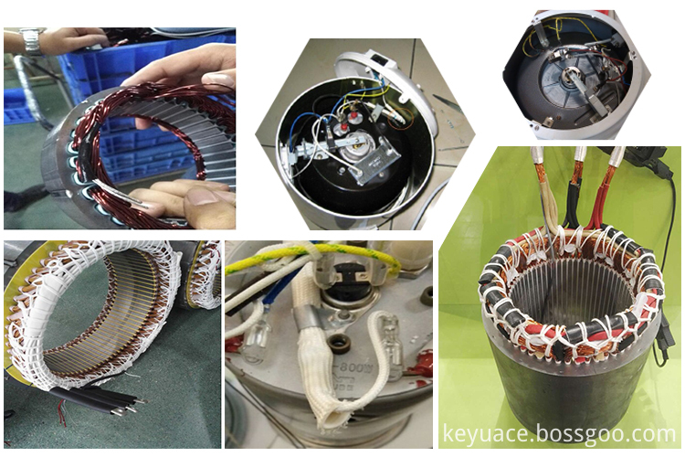
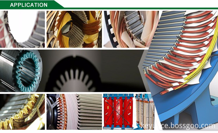
Silicone Coated Fiberglass Braid Sleeve for Cable Insulation, High Temperature Insulating Sleeve, Silicone Rubber Insulation Sleeving is made of braided e-grade glass fiber, then coated with silicone resin. Silicone Coated Braid Fiberglass Sleeving, Silicon Rubber Coated Fiber Glass Sleeving is widely used to protect electric cables,bundles and wires.Silicone Rubber Sleeving, Heat Resistant Fiberglass Sleeve , Silicone Fiberglass Sleeving , Fiberglass Silicon Rubber Insulation Sleeve it`s outstanding electrical insulation,self-extinguish,water & oil proof,resist to most acid and alkali,and anti-aging,which make this kind of sleevings to be a very good choice for electrical area using.
Product Characters:
|
Thermal Class |
H |
|
Size/inner diameter: |
0.5mm-50mm |
|
Colour: |
Black, red & blue, others on request
|
|
Working temperature: |
-60 degrees C -180 degrees C |
|
Rate voltage: |
1.5kv--7kv |
Structure:

Application:
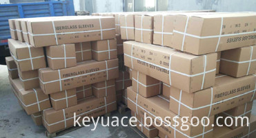
Packing and Delivery:


|
PART NO. |
ID/mm |
WALL THICK/mm |
||
|
Nominal |
Tolerance |
Min. |
Max. |
|
|
GWIT-005 |
0.5 |
±0.15 |
0.35 |
±0.65 |
|
GWIT-008 |
0.8 |
±0.20 |
0.35 |
±0.65 |
|
GWIT-010 |
1.0 |
±0.20 |
0.35 |
±0.65 |
|
GWIT-015 |
1.5 |
±0.20 |
0.35 |
±0.65 |
|
GWIT-020 |
2 |
±0.20 |
0.35 |
±0.65 |
|
GWIT-025 |
2.5 |
±0.20 |
0.35 |
±0.65 |
|
GWIT-030 |
3 |
±0.25 |
0.35 |
±0.65 |
|
GWIT-035 |
3.5 |
±0.25 |
0.35 |
±0.65 |
|
GWIT-040 |
4 |
±0.25 |
0.35 |
±0.65 |
|
GWIT-045- |
4.5 |
±0.25 |
0.35 |
±0.65 |
|
GWIT-050 |
5 |
±0.25 |
0.35 |
±0.65 |
|
GWIT-060 |
6 |
±0.25 |
0.35 |
±0.65 |
|
GWIT-070 |
7 |
±0.25 |
0.35 |
±0.65 |
|
GWIT-080 |
8 |
±0.30 |
0.5 |
±0.90 |
|
GWIT-090 |
9 |
±0.30 |
0.5 |
±0.90 |
|
GWIT-100 |
10 |
±0.30 |
0.5 |
±0.90 |
|
GWIT-120 |
12 |
±0.30 |
0.5 |
±0.90 |
|
GWIT-140 |
14 |
±0.50 |
0.5 |
±1.00 |
|
GWIT-160 |
16 |
±0.50 |
0.5 |
±1.00 |
|
GWIT-180 |
18 |
±0.50 |
0.5 |
±1.00 |
|
GWIT-200 |
20 |
±0.50 |
0.5 |
±1.00 |
|
GWIT-220 |
22 |
±0.60 |
0.5 |
±1.50 |
|
GWIT-240 |
24 |
±0.60 |
0.5 |
±1.50 |
|
GWIT-250 |
25 |
±0.60 |
0.5 |
±1.50 |
|
GWIT-300 |
30 |
±0.60 |
1 |
±2.00 |
|
GWIT-350 |
35 |
±0.60 |
1 |
±2.00 |
|
GWIT-400 |
40 |
±0.60 |
1 |
±2.00 |
|
GWIT-450 |
45 |
±0.60 |
1 |
±2.00 |
|
GWIT-500 |
50 |
±0.60 |
1 |
±2.00 |
High Temperature Insulating Sleeve
Fiberglass Silicon Rubber Insulation Sleeve,Silicone Rubber Insulation Sleeving,Silicone Fiberglass Sleeving,Silicon Rubber Coated Fiber Glass Sleeving, Heat Resistant Fiberglass Sleeve
KEYUACE Materials Co., Ltd. , http://www.insulationtubing.com
