Additive manufacturing, also known as 3D printing, is a manufacturing process that builds a part by adding materials, layer by layer. This process begins with a 3D model designed in the user's native CAD program. The part is then analyzed and divided into sections to create a build plan for the part.
Commonly used additive manufacturing techniques include stereolithography (SLA), selective laser sintering (SLS), direct metal laser sintering (DMLS), selective laser melting (SLM), and melt wire fabrication (FFF). There are other technologies.
There are many benefits to additive manufacturing. This includes shortening the delivery time of parts, making parts that cannot be made by traditional manufacturing methods, lighter parts, less waste, less operational skills, no tool changes between designs, and the use of multiple materials. ability. To date, a large number of amazing metals, polymers and polymer matrix materials and ceramics have been used in the field of additive manufacturing.
Additive manufacturing design method in SOLIDWORKS software
Features in SOLIDWORKS software can help identify design or geometry issues early in the design phase, reducing costs and saving time. Here are some of these features that will be prepared for general additive manufacturing parts design.
The features of SOLIDWORKS that this article will discuss include:
SimulationXpress (finite element analysis preview)
Print3D (3D printing module)
Geometry Analysis
Thickness Analysis
Undercut Analysis and Draft Analysis
DFMXpress (manufacturing feasibility analysis)
SimulationXpress (finite element analysis preview)
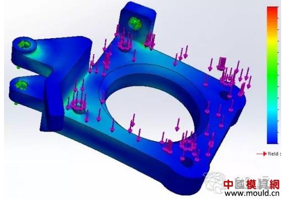
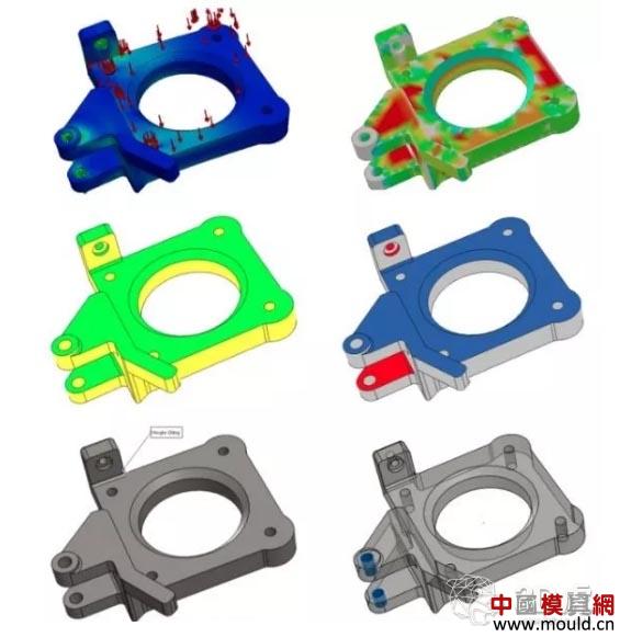
SimulationXpress is a free tool activated in SOLIDWORKS for the first finite element analysis in SOLIDWORKS software. SimulationXpress helps engineers and designers ensure that the parts they are designing will work as designed, which is important when deciding whether a prototype can work properly.
If a functional prototype, small batch production part, fixture, fixture or mold is required, plastic parts may not pass the stress or deflection test, then the material needs to be considered. One thing to note is that most parts created with FFF (made of molten wire) or similar technology are not 100% filled by default.
When talking about 3D printed parts, the fill percentage is usually used. Most internal materials will be layered in a matrix or lattice structure, rather than 100% solid or dense. The designed part does not have the strength of a 100% filled (fully dense) part, but the tool is still valuable when comparing the stress and deflection of the material.
Print3D (3D printing module)
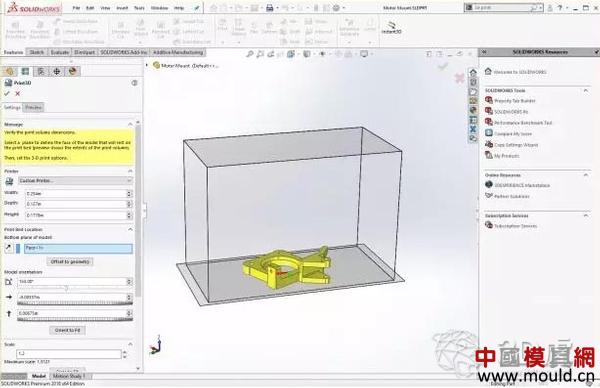
SOLIDWORKS introduced a feature a few years ago that makes 3D printers as easy as 2D printers (laser printers and inkjet printers) by printing to 3D printers in the application (SOLIDWORKS). This feature is not widely recognized by 3D printer manufacturers, but some printers support this feature, such as Makerbot.
Many 3D printing companies offer their own software. When considering that it has a thin wall inspector, a zoom function that ensures that the part can be accurately printed, and a volume checker that observes whether the part can be mounted on the 3D printer machine bed without change, this function Great value.
This feature will also attempt to adjust the orientation of the part to fit the build platform of the 3D printer. More than these features, Print3D (3D Printing Module) adds functionality to check where support may be needed. This is a feature-rich tool that should at least be used before sending a file to the printer. One ounce of prevention is better than a pound of treatment (prevention is primary, treatment is supplemented).
Geometry Analysis
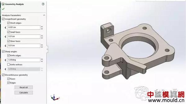
The Geometry Analysis feature identifies geometric shapes that may cause problems in other applications. These applications include finite element modeling, 3D printing, or computer-aided processing. You can specify the values ​​of the control parameters to identify these geometric entities.
These can be small sides, small faces or discontinuous sides or faces. No one wants the printer to try to create geometry that might fail, especially when it's easy to fix in SOLIDWORKS. Many of these errors occur around complex rounding operations.
Rounded corners are important to mitigate stress concentrations when manufacturing parts using some additional manufacturing processes. The figure below shows the geometry analysis being set for the part being designed.
Thickness Analysis
Thickness Analysis is a very important tool for all parts manufactured using additive or subtractive methods. Each 3D printing method has unique design guidelines for part size and wall thickness.
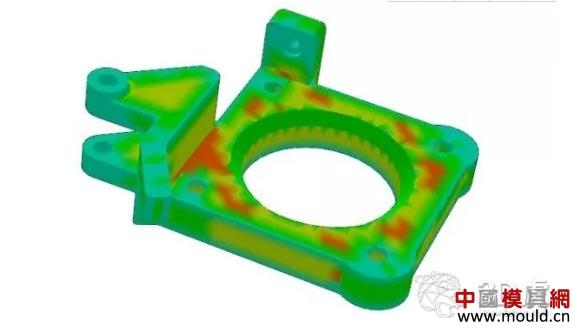
In SOLIDWORKS, these design criteria can be entered as parameters to generate feedback specific to the 3D printing process. Manufactured from additive materials of any material, very thin wall thickness can cause the parts to bend or fall. Thick walling is also a problem for some additive manufacturing processes. The same tools will also identify these areas.
As you can see from the image, SOLIDWORKS automatically detects the location of thin or thick walls in the part. These may not always be obvious, depending on the complexity of the design.
Undercut Analysis and Draft Analysis
These features are commonly used in mold design applications, but they are also very useful when viewing additive manufacturing applications. SOLIDWORKS users only need to define the "pull" direction or which direction the part will be constructed from, and define the angle threshold. SOLIDWORKS will do the rest.
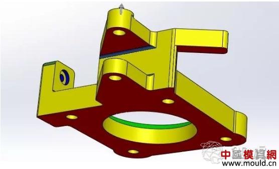
Support is usually required whenever there is a face with an undercut condition that is close to or exceeds 45 degrees. Since support should be avoided as much as possible, it is important for SOLIDWORKS to indicate when these conditions exist so that they can be resolved in the software.
Depending on the printing method, it is difficult to remove the bracket after printing and leave a very rough surface. In the image above, the red and blue surfaces require support, while the yellow and green surfaces do not require support. The reason why the yellow and green faces do not need to be supported is because they are within the angular threshold in the direction in which the part is built.
DFMXpress (manufacturing feasibility analysis)
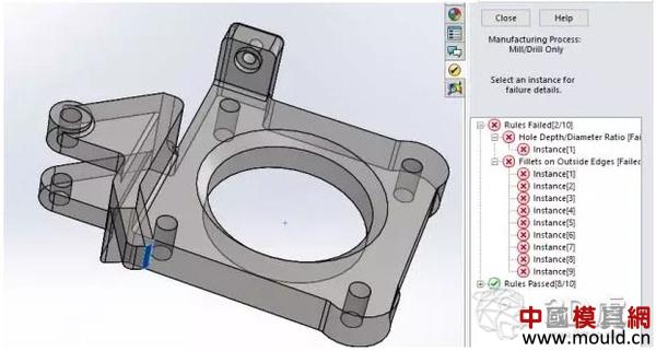
DFMXpress is a free tool that you need to activate in SOLIDWORKS software. This tool has nothing to do with additive manufacturing. In fact, it is geared to milling and drilling, which are all reduced manufacturing operations.
The value of this tool is to show where the advantages of additive manufacturing are in the case of difficult or impossible processing. The figure below shows the areas where the parts are designed, where it is difficult to use the reduced material manufacturing for milling or drilling.
SOLIDWORKS model for metal 3D printing
The above features can be applied to most manufacturing processes, including new processes known as bonded metal deposition (BMD). BMD is a printing technology supported by Desktop Metal's Studio system, through which a bundle of metal rods (metal powder mixed with a polymer binder) is heated and extruded to create 3D printed metal parts. All components of the system are secure, office friendly, and do not require a large device upgrade to run the printer. Not only can you prototype your shape and size, but you can also prototype your features. These are real metal parts that can be implemented according to design criteria.
These parts can be obtained in a few days using a desktop-based metal printing Studio system. Often, it takes several weeks to machine metal parts due to existing processing commitments or outsourcing. Other applications for parts of the Studio system are for small batch production, fixtures and tooling.
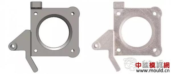
On the left is the SOLIDWORKS model, and on the right is the metal parts printed using the desktop-based metal printing Studio system. The same SOLIDWORKS model can be uploaded to the control software of the Studio system and printed. No STL or other neutral file formats are required.
to sum up:
SOLIDWORKS helps designers and engineers reduce part iteration cycles by identifying areas to redesign before printing. While many 3D printers have proprietary software for built-in geometry analysis, orientation modification, and geometry detection, finding these problems during the printing phase means that engineers have to modify between their CAD and print software and do the printing. Good preparation.
Using these tools, SOLIDWORKS users can discover problems that may exist during 3D printing in advance. Edit directly in the program. Therefore, it is possible to greatly improve the printing performance and reduce the reduction in the iteration period due to the printing failure.
Fiber Braided Hydraulic Hose,Hydraulic Braided Hose,Braided Hydraulic Lines,Double Wire Braided Hydraulic Hose
Hebei no one but god energy equipment co.,ltd , https://www.p-harcourtbrothers.com