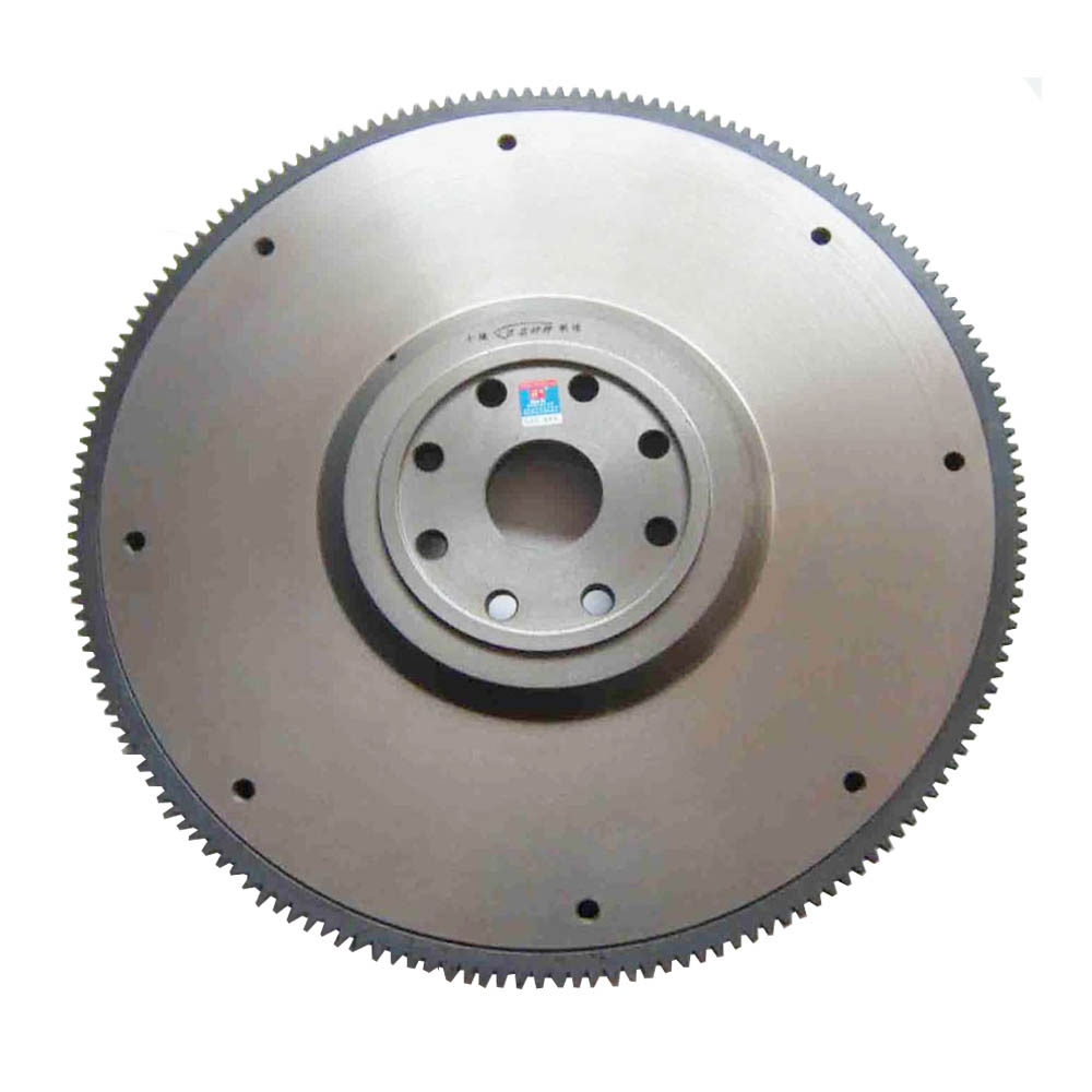
The flywheel is a large-scale cast iron inertial disk. It stores energy and supplies the demand for non-work strokes. It drives the entire curved connecting rod structure over the top and bottom dead points to ensure the homogeneity and output of the inertial rotation of the engine crankshaft rotation. The uniformity of the torque, by virtue of the inertial force of its own rotation, helps to overcome the compression resistance in the cylinder during starting and maintain the continued operation of the engine during short-term overload. The flywheel of a multi-cylinder engine should be balanced with the crankshaft, otherwise centrifugal force due to mass imbalance during rotation will cause engine vibration and accelerate wear of the main bearing. In order not to damage their equilibrium state during disassembly and assembly, there should be a strict relative position between the flywheel and the crankshaft, which is ensured by positioning pins or asymmetrically arranged bolts. The common damage parts of the flywheel are abrasion of the ring gear, ablation of the end face, flexure deformation and damage of the flywheel screw hole. The flywheel assembly is an important part of the engine, and its operation is up to hundreds of revolutions per minute, and its importance can be seen.
The main cause of the flywheel damage and maintenance
One, flywheel operation reasons
The flywheel has not reached the processing quality required by the drawings, and has poor balance performance. The amount of axial or circumferential radial runout of the flywheel end face is too large, so that the two planes cannot be joined smoothly and unevenly, causing the flywheel to work wavy.
When the flywheel rotates, there is a difference in rotational speed between the clutch and the flywheel plane due to the separation and engagement of the clutch, causing the two to slide relative to each other and causing wear on the working surface of the flywheel. The flywheel plane will also be locally hardened due to the high temperatures generated by high-speed friction.
When the flywheel rotates, the torque is large and the impact load is often accompanied by the transmission of torque, and the screw holes on the flywheel for a long time will cause damage and deformation.
The wear of the friction plate is reduced, the rivet head exceeds the plane of the friction plate, the face of the flywheel is scratched or grooved, or the friction plate is broken, and the rivet is loosened, causing the plane of the flywheel to be damaged.
Improper driving operation, or no free travel, or clutch disk pressure is insufficient, so that the clutch and the flywheel are often in a semi-clutch state, returning to the wear surface of the flywheel contact surface.

Second, the flywheel detection and maintenance
Detection of face circle run-out: Mount the dial indicator on the flywheel housing with the top of the watch head in the proper position on the flywheel face, and keep the crankshaft at a position where the front and rear axial clearances are eliminated (to prevent the crankshaft from rotating Axial turbulence is produced as a flywheel yaw.) Rotate the dial and turn the flywheel for one revolution. The reading of the dial indicator is the amount of circular runout of the end face. Generally, the circle run-out is not more than 0.15. When the overshoot is exceeded, copper pieces can be adjusted at the connection between the crankshaft flange end face and the flywheel, and the machining process is not used.
Detection of flywheel radial circular run-out: the contact of the dial indicator rests on the smooth inner ring or outer ring of the flywheel, rotates the dial, and rotates the flywheel one revolution. The reading of the dial indicator is the radial runout. Generally this value is not more than 0.1.
Finishing of the flywheel end: The end surface should not have cracks, burns, etc., and flexural deformation, the working surface should be flat, the surface roughness value should be low, the flatness error exceeds the technical requirements or there is a groove to grind and trim, but the repair The thickness generally does not exceed 2mm.
Maintenance of the flywheel ring gear: Common damages are start-up difficulties caused by tooth tip wear and breakage. Check the tooth of the ring gear for pits, scratches, etc. After the ring gear is worn out, it can be turned over. It is worn or broken and should be replaced with a new one. When removing the ring gear from an old car, heat the ring gear to the side of the engine with an oxy-acetylene flame, and then knock down the ring gear. Be careful not to hit the flywheel. When the vehicle is overhauled, the ring gear needs to be exchanged before and after, heating and pressing, and the heating temperature should be uniform when the hot gear is installed. The temperature must not exceed 350° C. to avoid annealing of the flywheel ring gear.
The flywheel fixing bolts are overhauled, and the joint surfaces of the crankshaft flanges and the flywheel are deflected or uneven, which loosens the connecting bolts. In addition, if the screw hole and the bolt clearance are too large or the bolt is not tightened according to the specified torque, the bolt will loosen. It is better to open the flywheel housing during inspection and use the crowbar to move the flywheel without any clearance.
After the overhaul of the engine, the flywheel must be tested for dynamic balance. Generally, the unbalance tolerance is not more than 98 g•cm.
NYP high viscosity heat insulation rotor pump
NYP high viscosity heat insulation rotor pump,High Quality NYP high viscosity heat insulation rotor pump,NYP high viscosity heat insulation rotor pump Details, CN
Botou Honghai Pump Co.,Ltd , https://www.gearpump.nl