I. Introduction
In the 3D design of parts, the design dimensions must take into account the total range of allowable variations. The sheet metal part designers need to consider the range of possible product dimension changes during the in sheet metal design process.
If the part dimension variation range is not suitable, such as if the tight tolerances, then a more precise manufacturing process is needed to ensure the accuracy of the finished product. Practical tolerances vary according to the design requirements.
However, this technology is available only from a few manufacturers and results in a significant increase in production costs. On the other hand, if the tolerance range is too large, it cannot guarantee the quality of the parts.
Hence, it's essential to determine an appropriate tolerance range for the sheet metal part size that takes into account both accuracy and cost.
II. What Is Sheet Metal Tolerance?
Sheet metal tolerance is a specified range that allows for variations in the design dimensions of parts. The manufacturing tolerances range defines the upper and lower limits of the variable design size of the workpiece. Tolerances are critical for ensuring the precision of sheet metal parts, and widely used in sheet metal fabrication.
The tolerance zone of the sheet metal tolerance is an area defined by the upper and lower deviations. Looser tolerances have a wider tolerance zone, while tighter tolerances have a smaller range of upper and lower limits. Tighter tolerances also mean that the dimensions of the workpiece are more precise. Like machining and 3D printing, this allows us to hold tighter tolerances.
III. Why Do We Need Sheet Metal Tolerance?
During workpiece manufacturability processing, slight differences in the metal plates can result in differences in the final product. Factors such as the sheet metal thickness, purity, texture, age, have a significant impact on sheet metal tolerances, and processing method of the material can impact the quality of precision sheet metal processing.
The tolerance range can vary depending on the material and thickness of the material. Below are some common tolerance range data:
| Material Thickness (mm) | Tolerance Range (mm) |
| 0.5 -1.0 | ±0.1 |
| 1.0 - 2.0 | ±0.15 |
| 2.0 -3.0 | ±0.2 |
| 3.0-5.0 | ±0.25 |
| 5.0-8.0 | ±0.3 |
Different materials have different tolerance requirements during processing. For example:
- Aluminum Alloy: Due to its softer nature, the typical tolerance range is around ±0.1mm.
- Stainless Steel: With its higher hardness, the tolerance range can be slightly larger, around ±0.2mm.
- Carbon Steel: The tolerance range is usually around ±0.15mm.
Having a certain tolerance range can improve the fit of the workpiece and potentially reduce production costs, as long as it is kept within a reasonable range.
Tool precise of size requires more specialized technology and equipment, which typically results in longer processing times. As a result, the use of reasonable tolerances in part design is crucial for determining the size of the final product.
IV. Relative Definitions of Tolerances
There are various forms of tolerances used in sheet metal processing, including flange length, width, sheet thickness, wall thickness, bends, curls, countersinks, hems, holes, slots, notches, and tabs. Parts need to maintain a uniform wall thickness throughout.
In addition to dimensional tolerance, parts also have differences between their actual form or mutual position compared to the ideal geometry, referred to as form tolerance and position tolerance, respectively.
Dimension tolerance refers to the allowable variation in size and is expressed as the difference between the maximum limit dimension and the minimum limit dimension, or between the upper deviation and the lower deviation.
On the other hand, position tolerance is the total variation allowed by the position of the actual feature in relation to the datum and can be further divided into orientation tolerance, positioning tolerance, and runout tolerance.
Tolerance grades determine the accuracy of dimensions and are divided into 18 grades according to international standard tolerances, with larger tolerance values representing lower processing difficulties.
IT01 to IT4 is used for the production of gauges and measuring instruments, while IT5 to IT7 is used for precision engineering applications, and IT12 to IT14 for sheet metal processing or stamping.
Tolerance symbols are expressed as an absolute value without a sign, with a smaller dimension tolerance indicating a higher dimensional accuracy.
The dimension tolerance is equal to the difference between the maximum limit dimension and the minimum limit dimension or equal to the difference between the upper deviation and the lower deviation.
V. How to Determine Sheet Metal Tolerances?
Part tolerance refers to the dimensions in the design and manufacture of parts that do not have tolerance indications or that are not part of the dimension chain and do not directly affect the fit properties.
The proper selection of part tolerance is crucial for the dimensional fit of parts in mechanical design. If the part tolerance is not chosen correctly, the part design dimension chain will be incomplete.
For parts with lower accuracy requirements, general tolerances can be used in the tolerance marking process. However, for parts with high precision requirements, the tolerance should be specified in detail in the mechanical design to ensure that it meets the actual needs.
The size, shape, location, and other requirements of a part are determined by its function. The selection of the tolerance grade should meet the design and quality requirements of the parts, taking into account factors such as processing cost, product performance, function, service life, and fuel consumption.
| Forming or bending | +/- 0.508 mm (0.020") |
| Bend to hole or feature | +/-0.254 mm (0.010") |
| Diameters with inserts | +/-0.0762 mm (0.003") |
| Angularity | +/- 1° |
| Holes | +/-0.127 mm (0.005") |
| Edge to edge | ±0.127 mm (0.005") |
| Edge to hole | ±0.127 mm (0.005") |
| Hole to hole | ±0.127 mm (0.005") |
| Hole to hardware | ±0.254 mm (0.010") |
| Edge to hardware | ±0.254 mm (0.010") |
| Hardware to hardware | ±0.381 mm (0.015") |
| Bend to hole | ±0.381 mm (0.015") |
| Bend to hardware | ±0.381 mm (0.015") |
| Bend to edge | ±0.254 mm (0.010") |
| Bend to bend | ±0.381 mm (0.015") |
VI. How to Do Tolerance Analysis?
The methods of tolerance analysis are mainly one-dimensional and three-dimensional. The one-dimensional method does not need to buy software, so the cost is low, while the three-dimensional method costs more.
There are also two different methods for one-dimensional tolerance analysis, one is the worst case and the other is the root mean square method (RSS). The second method belongs to the category of statistical methods, while the limit method is relatively simple.
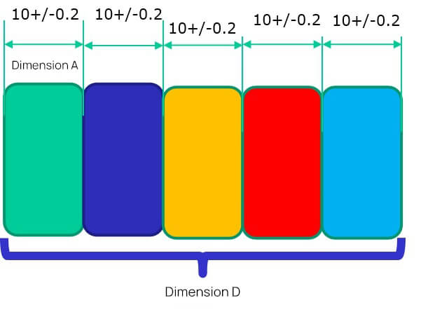
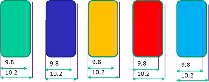
Upper dimension limit USL: 10.2+10.2+10.2+10.2+10.2=51
Lower dimension limit: 9.8+9.8+9.8+9.8+9.8=49, so the fluctuation range of dimension D is 49~51
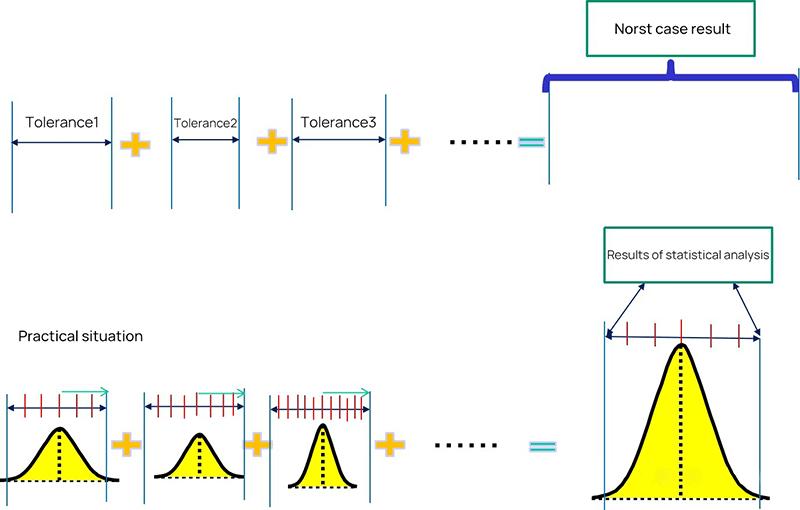
The limit method is the direct accumulation of each size boundary, while the statistical method is to consider the probability of each size to calculate the probability of each size after accumulation.
If we want to use the probability method to analyze, we need to know the respective probability of each dimension. The following is the distribution probability of dimension A. If it is a stable process, then it should be a normal distribution.
Then we need to know the overall distribution, and we need to know the two parameters of the normal distribution, the mean and the standard deviation.
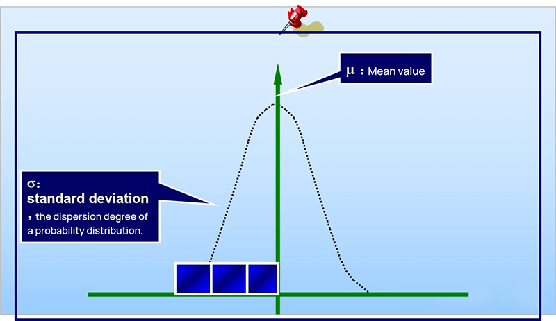
The standard deviation describes the discrete state of a distribution. It is a measure of the average dispersion of a group of data.
The standard deviation is large, indicating that there is a large difference between most values and the average value. The small standard deviation indicates that the difference between most values and the average is small.
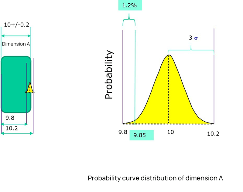
After knowing the mean value and standard deviation, we can see the distribution of this dimension.
As shown in the figure above, the mean value is 10 and the standard deviation is 0.067.
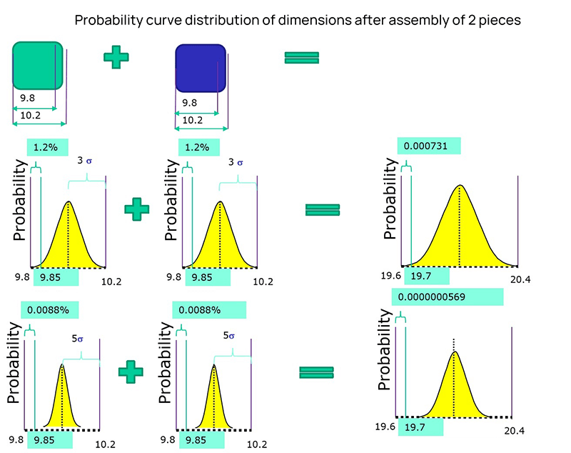
If two dimensions are accumulated, the mean value is the same, and the standard deviation is different, then the cumulative distribution is completely different. The results will be different if the distribution state of dimension fluctuation is different.
The original definition of tolerance is the way of limit definition, which can not describe a distribution well. Two parameters are required to describe a distribution, mean value and standard deviation.
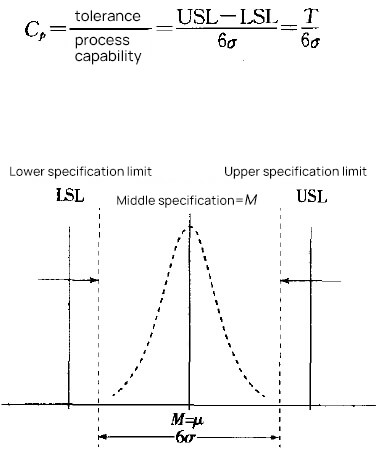
In order to associate with the original interval tolerance, another parameter - CPK needs to be introduced. To simplify the description, we assume that the center does not shift, CP=CPK.
As shown in the figure below, with a tolerance range and CP, you can know the standard deviation. Add the mean value and the normal distribution can be determined.
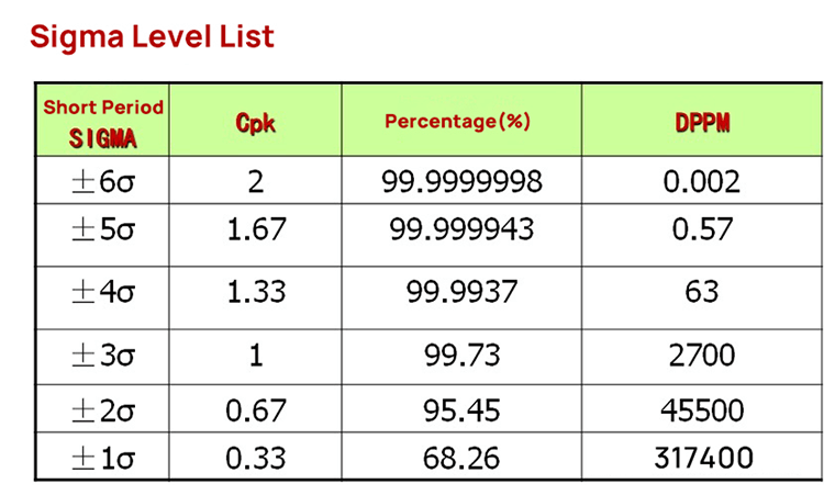
The following table shows the sigma level corresponding to CP (CPK). CP (CPK) 2 means 6 sigmas, and CP (CPK) 1.67 means 5 sigmas. When we know CP (CPK), we can get the sigma level, and we know the normal distribution.
Therefore, the mean value, tolerance range, and CP (CPK) should be known during tolerance analysis.

If we know the distribution of all dimensions in the dimension chain, we need to calculate the distribution of the total variation.
We need the calculation formula of RSS(Root Sum Square), that is, the square of the standard deviation of the normal distribution of the overall standard deviation is equal to the square sum of the standard deviation of each sub-distribution.
Therefore, the standard deviation of each dimension=the sigma level corresponding to the tolerance/CP, as shown in the figure below σ expresses the standard deviation.
σ²= (tolerance/process sigma) ²
Stacking different σ² is the total distribution of the overall standard deviation σ²
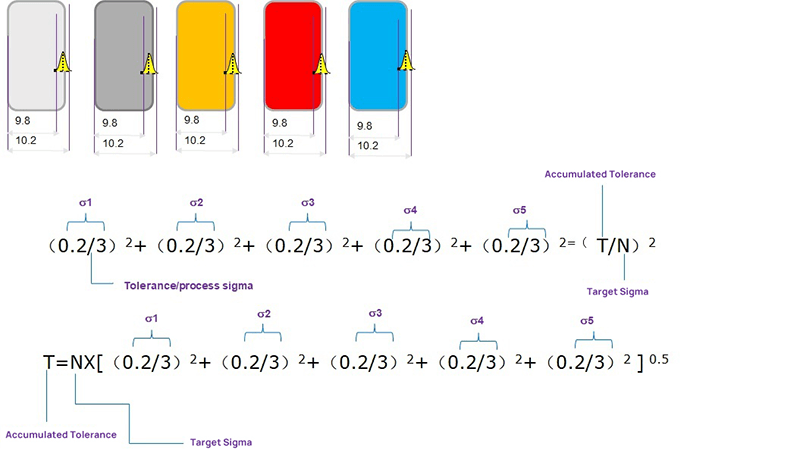
Finally, an excel template can be used to implement the analysis process. Fill the relevant parameters of each dimension into the table in the template to get the stacking results of the overall standard deviation.
VII. Industry Standards and Norms
1. ISO 2768
ISO 2768 is a widely used international standard for general tolerances in precision sheet metal fabrication. It covers linear dimensions, angular dimensions, and geometrical tolerances. The standard is divided into two parts:
- ISO 2768-1: General tolerances for linear and angular dimensions without individual tolerance indications.
- ISO 2768-2: General tolerances for geometrical tolerances without individual tolerance indications.
2. ASME Y14.5
ASME Y14.5 is an American standard that provides guidelines for dimensioning and tolerancing. It is essential for ensuring that parts fit together correctly and function as intended. This standard covers:
- Geometric Dimensioning and Tolerancing (GD&T): A system for defining and communicating engineering tolerances.
- Symbols and Notations: Standardized symbols for indicating tolerances on engineering drawings.
3. ANSI B4.1
ANSI B4.1 is another American standard that specifies preferred limits and fits for cylindrical parts. It provides guidelines for:
- Tolerance Grades: Different grades of tolerances based on the precision required.
- Fits: Types of fits (e.g., clearance, transition, interference) between mating parts.
4. DIN 6930
DIN 6930 is a German standard that specifies general tolerances for linear and angular dimensions in mechanical engineering. It is similar to ISO 2768 and is widely used in Europe.
5. JIS B 0405 and JIS B 0419
These Japanese standards provide guidelines for general tolerances in sheet metal fabrication:
- JIS B 0405: General tolerances for linear and angular dimensions.
- JIS B 0419: General tolerances for form and position.
6. Practical Application of Standards
Including practical examples of how these standards are applied can help you understand their importance. For instance:
- ISO 2768: Used in the automotive industry to ensure that parts from different suppliers fit together seamlessly.
- ASME Y14.5: Applied in aerospace manufacturing to maintain high precision and reliability of sheet metal components.
7. Example Table of Tolerances Based on ISO 2768
| Dimension Range (mm) | Tolerance Class (f) | Tolerance Class (m) | Tolerance Class (c) |
| 0.5-3 | ±0.05 | ±0.1 | ±0.2 |
| 3 - 6 | ±0.05 | ±0.1 | ±0.3 |
| 6 - 30 | ±0.1 | ±0.2 | ±0.5 |
| 30-120 | ±0.15 | ±0.3 | ±0.8 |
| 120-400 | ±0.2 | ±0.5 | ±1.2 |
8. Example of Geometric Tolerances Based on ASME Y14.5
| Feature Control Frame | Description |
| Position Tolerance | Position tolerance for hole locations |
| Flatness Tolerance | Flatness tolerance for surface control |
| Perpendicularity Tolerance | Perpendicularity tolerance for ensuring right bend angles |
VIII. Conclusion
This blog provides an overview of the basics of sheet metal tolerance, how to perform a tolerance analysis, industry standards and norms, etc. The design of parts is becoming increasingly complex and the tolerances required are becoming increasingly strict.
Sheet metal fabrication is the process of forming parts from a metal sheet by punching, cutting, stamping, and bending. To achieve the required sheet metal tolerance in sheet metal part design guidelines, manufacturers must use precise machinery during production.
ADH has 20 years of experience in world of sheet metal manufacturing processing machines, including CNC press brakes, shearing machines, and fiber laser cutting machines.
If you're looking to purchase sheets of metal processing machines, our product experts are available to provide you with detailed information.
Wuxi Yacai Precision Machinery Co., Ltd , https://www.yacaijm.com